What is AER (Automatic Error Recovery)?
Wednesday September 2, 2020By Mark Baumann
Director, Product Definition & Applications
MoSys, Inc.
As a characteristic of the MoSys Quazar and Blazar Accelerator Engine families of product, a feature that supports and non-supervised form of error recovery has been implemented. As the name suggests, the protocol that MoSys has developed (known as GCI Giga Chip Interface) has built into it the ability to recover from an error that may happen during signal transmission from the Host driving to the Accelerator Engine or from the Accelerator Engine back to the host.
Since the MoSys devices are using SerDes as the physical interface structure, it is a somewhat standard practice to protect the transmission of data across a SerDes lane by also implementing CRC code to pass along with data to insure that no issues of signal integrity (noise, coupling, CID [continuous Identical Digits], etc.) result in corruption of the transmitted data. When sending signals at 10GHz to 25GHz and higher it is a more common concern than when dealing with standard LVCMOS type signaling. This being the case, the definition of the interface protocol has provisions for handling this potential condition.
Just as an additional aside, the testing that MoSys has undertaken has shown the experiential error rate on boards that follow, “good layout practice” (see MoSys board design guidelines) is extremely low in the 10e-18 or lower. This has resulted in a single interface error every few years. However, if an error does occur, the protocol is designed to handle the issue without having to notify or involve any higher-level functions. It is left to the user if they wish to send notification to the higher functions.
The AER function will undertake the following steps:
- Build a frame (80 bits) to transmit across the SerDes lanes.
- Calculate either a CRC 6 or CRC12 (options) to send along with the frame.
- Transmit the frame from source to destination.
- Re-calculate the appropriate CRC value.
- Compare the sent and calculated value to insure they agree, and the transmission was cleanly completed.
- If an error is encountered. The receiver will notify the sender that it encountered an error.
- It will send this message multiple times to ensure the sender knows that a bad frame was received.
- The receiver will notify the sender of what frame had this error condition.
- The protocol then defines that the sender will “back-up” and resend frames starting with the one that was received with an error.
- If the re-sent frame is received cleanly, the interface will just return to normal functional operation.
- If the error is encountered again, the interface will stall, allowing the system to report the error to higher functions and the system will then decide what the correct, next step, course of action.
This mechanism has been implemented to insure a “reliable transport” layer. Meaning that if an error is encountered, the protocol that is implemented will automatically “back-up” and re-transmit the same data to attempt a “clean” transfer. Again, this is all built into the GCI protocol and does not require any intervention by the host.
If we are to look at the sequence of events in a bit mor detail it hopefully will become clearer as to what is involved and the overhead needed to support a reliable transmission protocol.
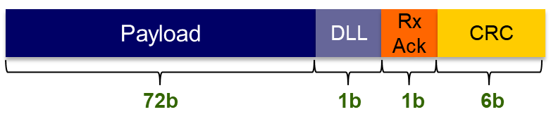
- 80 bit frame. For each transfer that is sent across the GCI Bus a “frame” is assembled. This frame carries 72 bits of data (address, control, data) bits, a bit (DLL) to define if the frame is carrying link layer data or transaction data, a Rx Ack bit to acknowledge the frame arrival, and 6bits which carry the CRC calculated for the frame (used to insure that the frame arrived cleanly).
- CRC Sent with Frame. As a standard procedure for SerDes links and to insure that the Data transmitted on the lane is received correctly, the frame carries a calculated CRC at the source and it is re-calculated at the destination the two are compare to insure that the data was not corrupted during the transmission from source to destination.
- Transmission. The Frame which now consists of 72 bits of data two flag bit sand 6 CRC bits are transmitted at the SerDes rate (for MoSys product that is between 10Gbps and 25Gbps) per lane.
- Re-calculate the CRC. At the receiving end of the transmission the CRC is re-calculated on the 74 bits (not using the CRC bits) and that calculated value is then compared to the transmitted value to ensure that the data was received correctly.
- Compare. The Sent and newly calculated CRC values are compared on a bit by bit basis to be used as the check for valid transmission.
- Error. If at this point there is a discrepancy between the sent and newly calculated CRC values, the protocol is designed to send back to the sender a notification (through the use of the Ack bit that an incorrect CRC was observed and that the receiving entity is requesting the sender “back-up” and re-send the data from the point in which the error was noticed and forward. This is performed by the receiving entity sending back a “frame ID code” that tells the sender the location of the data to start the re-transmission.
- Handshake. The protocol has a defined method to recognize that the receiver has identified an error. At that point the receiver will send back to the sender a series of frames that identify that an error has occurred and at what “Frame ID” the error was identified. This allows the sender to back up (in a circular buffer that can hold up to 128 transmitted frames) and re-send the data from the identified error frame and forward. This allows the error frame another chance to be received correctly.
- Sender is notified. The GCI interface has built into the handshake protocol the ability to utilize bits in the frame to send back notification that an error was received and to request a re-transmit or Start-of-replay to take place, before the resumption of new transmissions.
- Back-up. Within the GCI protocol is a way to embed information of what transmitted Frame had the error condition. This is already built in as part of the protocol handshake.
- Clean Re-transmit. If the effort to back-up and retransmit the frame(s) of data in which an error was seen is successful. The link with return to normal transmission of data. All of the error handling will take place without the need of intervention of the host. It is possible to notify the host but it is not necessary for the signaling and re-transmission to take place.
- 2nd transmission error. If, however upon retransmission of the data another error is identified, then the sending entity will be notified again and will have the ability to notify an upper level controller. The higher-level controller will then have the knowledge of this error and can handle this condition as defined by the system architect.
In reviewing this protocol, it is hoped that the benefits of Automatic Error Recovery can be understood. This is a feature of the MoSys devices and MoSys Application Engineering is available to explore the tradeoff of this or other Accelerator Engine features.
Additional Resources:
If you are looking for more technical information or need to discuss your technical challenges with an expert, we are happy to help. Email us and we will arrange to have one of our technical specialists speak with you. You can also sign up for updates. Finally, please follow us on social media so we can keep in touch.